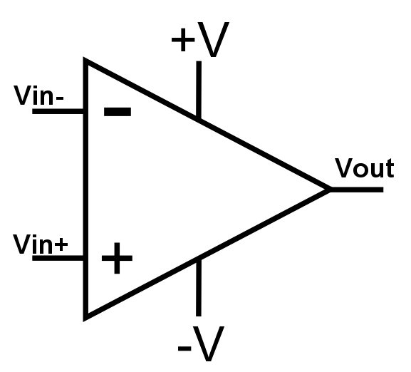
An OP Amp or Operational Amplifier is a differential input, single ended output amplifier. The gain of these amplifiers is determined by an external feedback element which is usually a resistor network. The symbol for a OP Amp is below:
The name “Operational Amplifier” originated from the fact that devices of this design were originally used in analog computers to help perform mathematical operations such as addition, multiplication, and many more.
An ideal OP Amp has the following attributes:
Infinite open-loop gain.
Zero input offset voltage.
Infinite input impedance, and therefore zero input current.
Infinite voltage range available at the output.
Infinite bandwidth with zero phase shift and infinite slew rate.
Zero output impedance.
Zero noise.
Infinite Common-Mode Rejection Ratio (CMRR)
Infinite Power Supply Rejection Ratio.
These ideals may be summarised by the two “Key Rules” which should be remembered:
1. In a closed loop the output attempts to do whatever is necessary to make the voltage difference between the inputs zero.
2. The inputs draw no current.
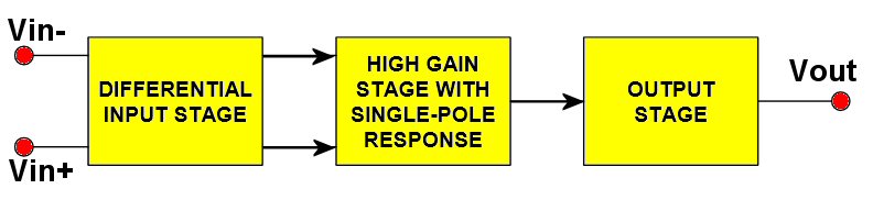
Internally, the op amp is basically a three-stage amplifier circuit using multiple transistors. The three stages are as follows:
1. A differential stage that makes a comparison of the two input voltage signals and outputs the amplified difference value.
2 A high gain stage that receives the differential stage output and amplifies it further.
3. An output buffer stage that may also serve as a “power amplifier” stage for driving large capacitive or resistive loads and for providing a low output impedance.
The input impedance of an Op Amp is made to be very high so that very little current flows (ideally no current) in the signal inputs, and thus any preceding circuit providing the input signal has very little load imposed upon it and very little power is consumed.
Unlike other signal boosting amplifier circuits, the Op Amp circuit uses no coupling capacitors at the input or output terminals. This direct coupling method allows the Op Amp to work with both DC and AC voltages.
The voltage gain of an Op Amp in an “Open Loop” configuration (i.e. no output feedback is provided) is typically very high, in the range of 10,000 to 100,000, and some may even exceed 1,000,000. For most circuit application a closed loop configuration is used in which feedback to an input terminal is provided from the output using a resistor network.
Basic Inverting Amplifier
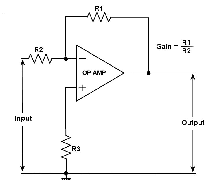
In the above circuit the input impedance is almost equal to the resistance of R2, since one side of this resistor always remains at about ground potential. To minimise the effect of small currents flowing in to the amplifier inputs the value of R3 should equal the value of R2 in parallel with R1.
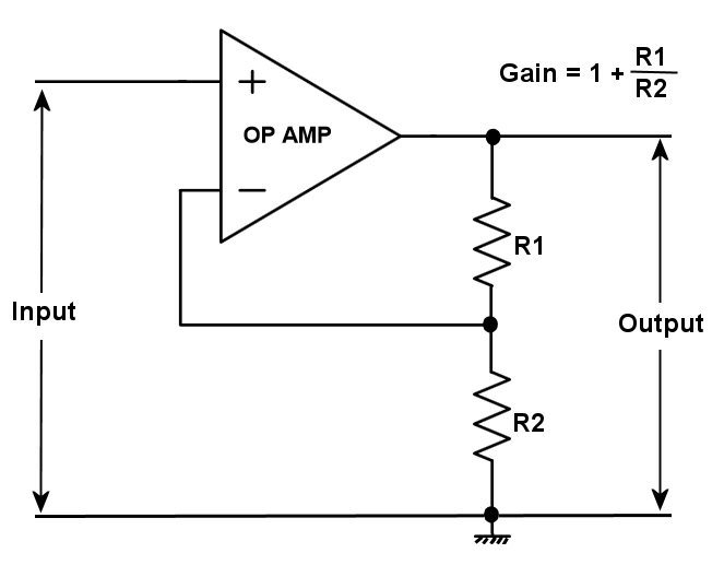
Basic Non-Inverting Amplifier circuit
Op Amp Buffer
(voltage follower with 100% negative feedback)
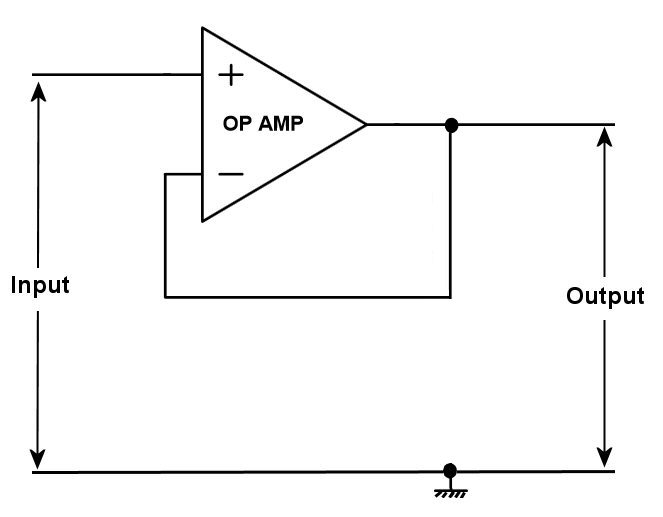
The voltage follower above is sometimes called an “impedance converter” as it converts the high input impedance to a low output impedance.
OP AMP TOPOLOGIES
The above circuit examples relate to voltage feedback Op Amps but there are two basic Op Amp topologies, namely; voltage feedback and current feedback.
Hi there, I am sorry to bother you. I am building my first electronics project with inspiration from your Millivolt meter design and help from a coder friend. It is an auto-ranging voltage and current meter that will hopefully measure up to 80VDC and 200A using a hall effect sensor (i also have a shunt if this isn’t sensitive enough). I have designed a circuit and a schematic and have tested a few of the principles. I am just about to breadboard it and have realised that my electronics knowledge is quite limited. This is my first time using op amps. Would it be possible for you to look over my schematic and let me know if I have forgotten anything or if I am way out? I have left out the peripherals. The circuit uses 2 ADCs with 4 differential pairs being measured and logged by an arduino uno. I have designed the schematic on a program called Fritzing, but i am sure I can export in any format. Thanks, Blake Sanders