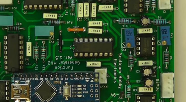
In this project we will design and build a Function Generator. The Frequency will be controlled by using a rotary encoder and functions controlled by push buttons. A 20 x 4 LCD and Arduino Nano will also be used for the user interface and control.
Below are the download links for this project:
Ardunio software version 1.7: http://www.scullcom.com/Function_Gen_Mk2_ver1_7.ino
Schematic, Layout and Parts List: http://www.scullcom.com/Function_Generator_Mk2_files_Part1.zip
PCB Gerber files link below: http://www.scullcom.com/Fun_Gen_Mk2_Main_PCB_ver1_5_gerber_files.zip
PCB size is 100mm x 99mm – double side print.
Hi Louis,
Is there any chance you might consider sharing the kicad project? I’d like to try and optimise the layout & spacing so that I can cut it reliably on my slightly dubious aliexpress milling machine.
Thanks again for the excellent projects.
Jay
Hi Louis, I hope the book is coming along well. I know i speak for myself and many from youtube, that we miss your vids and amazing contrabution to the EE commumity. Hahahha anyhow happy new year !! Hope to see you back soon.
Kind regards
Peter – liverpool
Hello!
This is Amber from Banggood.com, is there a chance to work with you?
Amber
Louis haven’t seen or heard you for a while hope everything’s OK with you.
Hi Paul,
Thanks for your message. I have been busy of late with other work so have not had much spare time for my YouTube channel. I am in the process of writing a book about family history which is taking longer than I first thought. Hope to get back to electronics projects soon.
Best regards,
Louis
Glad your ok, spare time I’m told in retirement most are more busy than when at work, with only 12 months to go I’m wondering what’s in store. I sometimes don’t have the drive to go into my workshop for a couple of months, then I’ll just go in and spend all day in there. Wow writing a book if it’s going to be published let me know please nothing nicer than a good book to read.
Paul
Hi Louis,
I know this is off the Function Generator Mk2 subject but I hadn’t seen any recent activity on the Electronic DC Load section, of which it seems I was late to the party. I was hoping you could answer a question on it. I wanted to know if you thought your DC load unit software could be modified or added to, in order to measure farads for supercapacitor experiments? These are generally low voltage but rated in a few to many farads. My software experience is 8085 assembly but that was about 30 years ago but it seems to me it could be done by data logging amperage and also the voltage rise until it tops out and then do the capacitance calculations.
Thank you for your time
Hi Mark,
Thanks for your comments. I am sure you could add a function to the Battery Capacity mode so that it could be used to check supper capacitors. I may have a look at adding it as an option later.
At the moment I am busy with some family projects.
Best regards,
Louis
Mr. Scully,
I have completed the hardware build of millivolt meter mk2, but I can’t get the
software to work. The LiquidCristal_I2c was removed from bit bucket, and is no
longer available. They (Arduino group) suggested that I use the software accociated
with the LCD chip set, which is now called just ‘LiquidCrystal’, which I did. I changed
all of the previous references to LiquidCrystal. This does not compile. I sent a request
to the Arduino support group, and they can’t find the problem either. Could you just send
me some working code that I could up-load. Something that you know that works.
My code fails at the very last routine (read back 4 bytes) at the line before the left
curly bracket ‘{‘.
Best Regards,
Paul Hoffman
Hi Louis,
Thanks for always making great videos. I love that everyone’s concerned about you not posting in a while -but good to see you’re just busy with family projects.
Just wondering if you had an email address I could grab? Really want to run something by you.
Thank you!
Hi Louis I hope that you are well?
Is there any chance of you providing the psu details?
I have no means of powering the unit to carry out the initial set-up.
Hope to see you back soon.
Regards
Mark.
Hi Louis,
I hope you’re still alright, I miss your amazing YouTube content!
Cory
Louis haven’t seen or heard you for a while hope everything’s OK. and miss the YouTube vids.
also the website seams to missing some *.pdf files, and *.ino files as-well, for various projects.
Where did Louis disappear, why did his channel freeze?
If you read the above comments you will see Louis is busy on family projects, I’m sure he’ll be back at a time of his choosing, we all miss him, and his projects.
Louis , just a welfare check on you,
Hope you and the family are keeping well, in these difficult times, are you getting your daily exercise which is important, for the body and mind,
Are you eating well, I hope the book is gong well, seems quite a task.
73 Paul M0BSW UK Radio Amateur
XR2206 seems to be “unobtanium”, any thoughts of a MK-3?
You can actually get them (real ones, not inferior Chinese knock-offs) from Jameco:
https://www.jameco.com/z/XR2206CP-EXAR-Corporation-IC-XR2206CP-Monolithic-Function-Generator_34972.html
Louis,
Missing your YouTube channel mate…..hope all is well and you can get back to it soon.
Ian.
Hello, has anyone made this generator and modified the software to display the frequency in clear? Thanks in advance (translated)
Hi Louis,
I am a new subscriber to your YouTube channel and would like to congratulate you on it.
I have always had an interest in, but very little knowledge of, electronics and you channel has sparked taking it on as a new hobby. I have bought myself an oscilloscope, and Arduino project kit and I have signed up for an online electronics course, which is over 120 hours of study.
I have decided that I am going to build your function generator, as I feel it would be a good addition to my equipment. I have ordered the PCB and am now in the process of getting all the component, as I don’t have many, being fairly new to electronics. It is going to be quite an expensive build, and I’m sure I can buy an off-the-shelf one for much less than it will cost to build it, but where’s the fun in that?
Going through your parts list I have noticed that there are a few omissions, so I have amended the pdf. Please let me know if you would like me to sennd you a copy, so you can check it and upload it on YouTube and your website.
Whilst I’m excited about the build I don’t understand the power input side of the function generator. The schematic shows both +9v, -9v and 5v inputs together with a ground. Do I, therefore, need two transformers? Also, in your video, when you do the intial start up, you mention a supply of 6v. Can you please enlighten me.
Can I wish you a Happy New Year and hope that 2021 is a prosperos on for you.
Many thanks
John
I’m trying to send a message to ‘nb2k’ who wanted information on Major Hexter-Stabbins from the Worcestershire Regiment but that site doesn’t allow messages to be left. I gather it’s your site and this seems to be the only way to get through. The query URL is http://www.worcestershireregiment.com/forum/viewtopic.php?t=1263 from 2009, and I have an item on the Baron which may be of interest. We stayed with him for a few weeks and have a newspaper cutting ‘nb2k’ might want.
I just stumbled over this site and youtube channel. Mr Louis is so nice and his videos are so instructive. I love these small projects such as the millohm and millivolt meter. I’m already planning to build some of them! Even though the videos are a few years old now, they are exactly what I need to get through the isolation in these hard times. Thanks a lot and please come back.
Dear Louis
I hope you’re well and will be able to make part 2 of this project. Could you or any existing builders of this project advise its current draw? I have a Traco DC-DC converter that will give me a split supply of +/-15V 300mA and a 7909 linear regulator for -9V.
Mouser has all the IC as 1 offs except the XR2206.
Thanks
I’ve built the function generator Mk2 and it’s working. I set max count to -5.73V and then min count was -3.195V straight off.
The Arduino Nano clone needed to have the Tools>Processor>328P ( older boot loader) enabled for Louis’ script to upload.
Around 270 degrees phase [negative part of cycle], the sign waves have a slope which I can’t adjust out. THD and Symmetry controls cured the clipping. I used a 50 ohms through termination on the scope. The output is connected to 4 inches of 50ohms co-ax and a BNC socket; pig-tails on both ends make the screen connections.
The NE5532P op amps supplied by Mouser have no pin 1 dot or end notch. With the part identity writing in the same orientation as the other ICs they seem to be working OK.
Current draw for the generator, DC-DC converter and a LM7805 regulator was around 240 mA when I was running the board at ±9V. This looked very noisy so I’m running the generator off a lab power supply at ±6V.
It’s important to get a plain EC11 rotary encoder to avoid extra switch bounce resistors.
https://www.farnell.com/datasheets/1837001.pdf shows pinout
Looking at the board edge with the label ENCODER in reading direction, from left to right connections are | Gnd to 5 or D| R10& R20 to 4 or E| R28 to 1 or A | Gnd to 2 or C | R30 to 1 or A.
I really hope, like all the viewers, to see part 2 in 2021, Louis with a nice clean, split power supply and help optimising the waveforms. I guess there’ll be a frequency readout and peak to peak measurement one day.
Thank you very much.
Hi can anyone tell me what sort of current the power supply needs to provide to run this project?
Lol, love some of these comments. “Yes I know you are busy with writing a book I totally understand, by the way can I get your email I want to run something by you”. Idiots like this is what caused Louis to go dark. One stupid pointless question after another.
One could easily argue that your comment is as pointless as their questions. Maybe you should be more careful with your use of the word idiots.
Hi
I love your youtube channel because your projects are the best, I would like to know how to improve the milimeter project to zero the 5 and 6 digits.
Hi,
This is Jackie, global marketing manager from TESamrt. I’ve been following your account since this year and loved your video style. We thought you would be a perfect fit for our latest campaign.
We’re giving away free KVM Switch samples, in exchange for 1 Youtube video promoting your experience with our brand.We will also give you some commission based on your follower base.
Are you interested in participating?
Let me know,
Jackie
https://www.tesmart.com/
hello sir, we try to contact you to get more information on your excellent projects.
Please contact me at marcdegier@gmail.com
Can anyone confirm if Mr Scully is alive and well. He has simply vanished. I find it hard to believe someone this prominent can pass away without some sort of tribute or obituary.
I hope my fears are unfounded and the man is just busy.
Unfortunately you are right. Mr. Scully passed away some two years ago from respiratory failure AFAIK.
R.I.P.
Worth checking the comments on the YouTube video. There are notes from Nov 2022 that indicate he is “doing OK, just getting a little older” and working on other projects.
I’m terribly sorry to hear that. I really enjoyed his videos.
Wow. Time does slip away.
Mike Yancey, KM5Z
Greenville, Texas, USA
Hi Guys, Happy Xmas to everyone. It’s been quiet on here for a while so I thought I’d post.
Has anyone had any luck powering this project I’ve not tried yet despite building it a couple of years ago. What is thyew best way to power up for initial setup? Is there any power supply details for this out there pcb or what not. I was in contact a few years ago with a guy in the USA who had managed to get hold of the pcb for this projects and build it. (power supply pcb)
Has anyone got hold of the power supply details they could perhaps sent me them I would be very grateful. all the best for 2025 when it gets here. markpettitt46@gmail.com.
Mark.