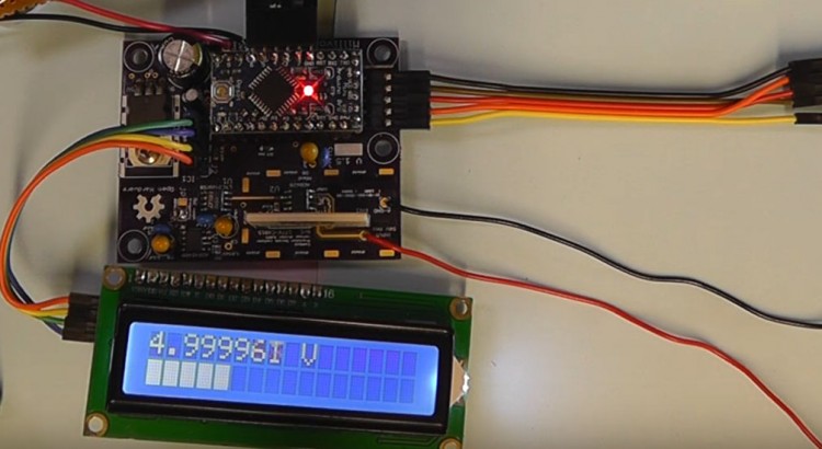
This version of my Millivolt Meter is an upgrade on my previous project version and uses a small PCB and Arduino Pro Mini.
The display now uses an I2C interface. The build now includes a Hold Reading and Bar Graph display. In addition the calibration method has been upgraded to use a 5 volt reference source. The latest version of software has also been improved resulting in a faster refresh rate. Below are links to download the latest software and also a zip file which contains PDF’s for the Schematic, Parts List, Wiring Diagram, Plate and Drill Templates and Front and Back Panel Artwork.
I really like this project, it is very informative! I have a thought, I am new to electronics and I am wanting to combine a volt, ohm and amp meter into one, how would I go about doing that?
Full disclosure: It takes me 1.5 hours to watch “60 Minutes”.
But isn’t what your are describing called a multi-meter? and what about a capacitance meter that can test leakage and ESR?
Also now we are making this I want to add the following features please:
Continuity, Conductance, Inductence, Temperature, Diode and Transistor.
And less important but still would be liked:
Decibel, Duty cycle and Frequency.
Now I don’t know David Smith, but I’m willing to go out on a limb and say both he and I are willing to pay up to $82.98 USD for such a device. Louis how long will it take you to design this and share with us? in the mean time I’m going to go door knocking to find additional buyers
is there a bi-polar input version ?
could a voltage referance and op-amp be added tosupply 2.5 v bias?
Hi,
First of all can I just say “don’t stop making these projects videos”.
I’m returning to hobby electronics after a 25 or so year break and things have changed a lot, so my learning curve is very steep at the moment and your videos are, in my opinion, some of the best on you tube.
I have been following the millivolt meter project and I have a couple of questions I hope you can answer for me.
1. The mk2 version uses an external 5v reference for calibration, can the internal 4.096v reference be used instead? i.e a switched connection between the output of the ic and the +ve input on the board.
2. The mk2 version uses the same caddock resistor network as used in the earlier versions, but the divider has been reduced from 9M / 1M to 900k / 100k is there an advantage?
Hi Julian,
Thanks for your kind comments.
With regards your questions:
1. Yes you can use the internal 4.096V reference for calibration.
2. The new small PCB used in Mk2 was designed by one of my viewers who for some reason designed his print layout to use the 900K / 100K divider of the Caddock Resistor Networks. Originally I used the 9M / 1M option. You can use either but the latter option gives you a higher input impedance which is better. To use the 9M / 1M option on the new Mk2 PCB (from OSH Park) you will need to raise the Caddock Resistor Networks off the PCB slightly and then use wires connecting the 9M / 1M sections to the PCB.
I am currently working on a new project which will be a Function Generator with some new design features. I am currently designing a PCB for this new project. Hopefully, I shall have it finished in a few weeks and will film it for my You Tube channel.
Kind regards,
Louis
Hi,
I need help!
I have created a perf board variation of the mk2 millivolt meter and it doesn’t work. I have placed a pdf of the circuit board layout in the link below.
https://drive.google.com/open?id=1WF7aGF4wwLYKMQYC_pfe-S47Mx0pNHwQ
The 3 smd ics, are mounted to smd to dip adapters to make it compatible with 2.54mm pitch perf board. The AD8628 is a SOT23 package, the ADR4540 & LTC2400 are both 8 pin.
The 10 to 1 voltage divider is created using 6 x 232K 0.1% resistors in a series + parallel (3R, R/3) layout, give 696K & 77.333K network.
The connections to the arduino nano are made via pin headers.
So the circuit / software runs but the voltage reading is wrong and inconsistent, ie 5V displays as anything between 5V and 1050V.
If you calibrate it to a 5v reference it gives a calibration offset of around 4200.
Without the op amp buffer connected, the 4.096V reference from the ADR4540 can be measured as 4.096V, with the op amp connected it measures around 0.83V.
Any help would be greatly appreciated.
Hello Louis,
I have part built the Mk2 version of the MillivoltMeter. I have yet to add buttons for cal, etc, but otherwise
it is working OK, showing sensible voltage readings.
However, one issue:
I am using the PCF8574A expander board for I2C Bus, to drive the display.
The address for the A version, with no resistors at A0,A1,A2, in hex is 0x3F, not 0x38.
I found correct address from the PCF8574A datasheet.
Perhaps other readers should be aware of this.
Best regards.
Hi Louis, I enjoy your videos immensely, and find them enlightening. I’m a retired EE, and occasionally help a friend who teaches a senior EE project design class at a local university, by presenting a guest lecture on PCB design. If possible, I’d like permission to use a couple of your schematics as examples in my talk, with attribution to you, of course. Specifically, your series on the design of the Milli Voltmeter and the Milli Voltmeter MK2 points out some pitfalls of low voltage/high accuracy circuit design.
Thanks in advance, Craig Ross
Hello Mr. Louis, the circuit is very interesting and excellent. I want to ask a question about how the circuit works. Why does it show a value of about 50 millivolts when the input circuit does not have a voltage to measure, while it should be a value close to zero or within Show microvolts?
Hello Mr. Louis, the circuit is very interesting and excellent. I want to ask a question about how the circuit works. Why does it show a value of about 50 millivolts when the input circuit does not have a voltage to measure, while it should be a value close to zero or within Show microvolts?