Part 1
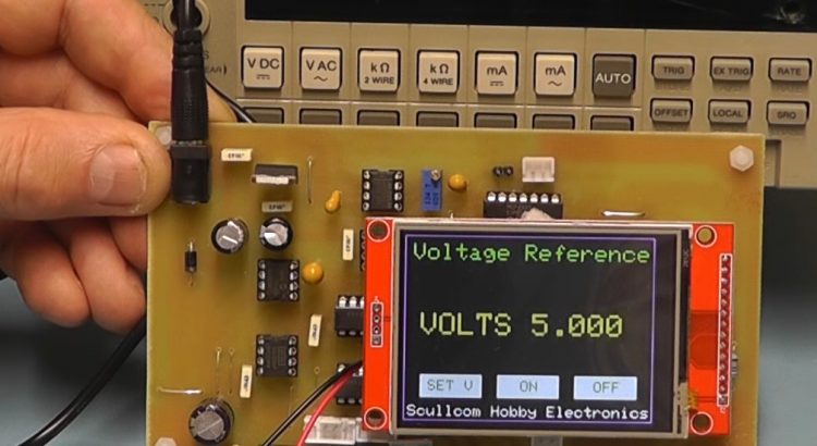
In this project we will design and build a DC Voltage Calibrator, providing a voltage range from 0 to 10 volts in 1 milli volt steps. The user interface will be a TFT display with touchscreen.
Below are links to version 1 of the software for the Arduino Nano. Also a zip file which contains the schematic, PCB artwork (Version 2) and component layout:
http://www.scullcom.com/DC_Voltage_Calibrator_Ver1.ino
http://www.scullcom.com/DC_Voltage_Calibrator.zip
Parts List link below:
http://www.scullcom.com/DC_Voltage_Calibrator_Parts_List.pdf
Below is a link to my KiCad files for this project:
http://www.scullcom.com/DC_Voltage_Cal_KiCad_files.zip
Part 2
In part 2 of this project we will make a number of improvements and build the unit in to a project case and carry out some tests.
Below are links to download the latest software version plus some zip files with all the project information including schematic, PCB artwork, wiring layouts and parts list plus project case template and front panel artwork:
http://www.scullcom.com/DC_Voltage_Calibrator_Ver2.ino
http://www.scullcom.com/DC_Cal_1_024V_option.zip
http://www.scullcom.com/DC_Cal_TFT_Nano_Module.zip
http://www.scullcom.com/DC_Cal_Front_Panel.zip
For the project case simply search on eBay for “7.8”x6.9″x2.7″ Plastic Electronics Instrument Plastic Case Box Shell w/ Handle”
Also available from www.banggood.com as:
7.8 x6.9 x2.7 plastic electronics instrument plastic case box shell
In part 3 we will use new double side PCB’s and improve the accuracy of voltage reference below 2 volts. We will remove the need for calibration of the 1.024V Ref. Also a new battery option will be added. You can download the latest version of Arduino software, schematics and KiCad files from the links below: http://www.scullcom.com/DC_Voltage_Calibrator_Ver6.ino
http://www.scullcom.com/DC_Calibrator_schematics.zip
http://www.scullcom.com/DC_Cal_Battery_Module.zip
http://www.scullcom.com/DC_Calibrator_main_PCB_KiCad_files.zip
http://www.scullcom.com/DC_Cal_TFT_Nano_module_KiCad_files.zip
http://www.scullcom.com/DC_Calibrator_Battery_Option_KiCad_files.zip
Parts list can be downloaded from the link below:
http://www.scullcom.com/DC_Voltage_Cal_Parts_List.pdf
Below are links to download the latest Gerber Files for PCB production:
http://www.scullcom.com/DC_Cal_Main_PCB_2_2a.zip
http://www.scullcom.com/DC_Cal_Display_Nano_2_0a.zip
This a great project that I intend to take advatage of. As an enhancement to assist with the calibration of the higher voltage ranges, could a further stage, perhaps utilizing a high voltage op amp (and of course, a suitable power source) be added to take the voltage up to about 100 volts?
Louis
Do you have plans to get any more pcbs (for the DC Voltage Calibrator)?
Thanks
Peter
Hi Peter,
I will have a small quantity of the DC Calibrator PCB’s next week.
Regards,
Louis
Hi Louis,
I’d like to order the PCB’s Please let me know the cost incl shipping to usa.
Thanks, Rudy
Hi Louis,
I’d like to order the pcb’s. Please let me know if you have any available.
Thanks, Rudy
Louis, I only discovered your youtube channel in the past week, but was extreemly impressed with the DC load and DC voltage calabrator. I see that you offered boards for the voltage calabrator at one point and was wondering if you still had any available? I haven’t finished the DC load videos yet, so im not sure if you made any boards for that one, but if you did I would be interested in that as well.
Thanks,
Ron
Hi Ron,
I will send you an email with regards the PCB’s for both the DC Calibrator and DC Load projects.
Regards,
Louis
I would also like to get a PCB if you still have any.
Located in Arizona, USA
Hi Louis,
I have assembled your DC calibrator as it works very fine, great project.
But i have tested two similar display, one have a touch chip XPT2046 and works fine, another have a HR2046 chip, and touch don’t work!
I discovered that the touch works but x and y position are reversed, as the image were upside down.
I have to change some settings in yours sketch?
Best regards
Hi Vincenzo,
Yes I have found some TFT display sold on eBay have the touch screen element in reverse.
Regards,
Louis
I solved with tft.setRotation(3)
Which is the max value for reference input?
Glad to hear.
Regards,
Louis
I am having the same problem with my screen how do I apply the command where should I put it thanks for any help …ps I do have the xpt2046 but the touch is not where the buttons are? It’s like upside down and mirrored thanks for any feedbac
Louis, you have done a great job with this project – congratulations…
Watching the video on voltage setting I thought the use of the touch screen was a bit fiddly in operation. Would it not be better to use a rotary encoder?
While the touchscreen method does avoid accidental changes to the output setting – which could be possible when using a continuously variable control, it would not be disastrous imo – though it might if calibrating an analogue meter depending on the range setting.
What do you think about this idea as a possibility?
Or, alternatively, if sticking with the touch screen, use up and down arrows on the screen to increase or lower the output voltage.
Either of my suggestions would probably require the step resolution to be increased as it takes some time to scroll up or down in 1mV, 2mV or 4mV steps. Who requires anything better than 100mV steps?
Hi Louis,
Yes, I would be interested in getting a set of the
pcb’s required for this project.
I live in the States so, let me know the overall cost + shipping to Calif (Zip 95678).
Thank You Sir,
Grant
Hi Grant,
I have sent you an email with details.
Regards,
Louis
Hi Louis,
I am interested in getting a set of the pcb’s required for the project. I live in the States (Zip 21032).
Best regards,
Robert
Hi Robert,
I have sent you an email with details.
Regards,
Louis
Hi Louis,
I’ve been having a youtube marathon watching your projects after discovering your channel. Absolutely fantastic content. Do you still have any PCB’s for the DC Load Project and this (DC Voltage Source)? I’m located in the UK.
Kind Regards,
Simon.
Hi Simon,
I do have a few spare DC Load PCB’s left. They are version 9.3 which include some improvements.
I will send you and email with details.
Regards,
Louis
Hello Mr. Scully,
I’m trying to contact you regarding The Worcestershire Regiment. Its an amazing source of history and it has helped me very much already.
I know this is not what your Scullcom website is about but there didn’t seem to be a way or emailing you from The Worcestershire Regiment site.
I’m wondering if you could assist me in finding people who I could contact, who might be able to help me?
I’m a 3rd year historical stone carving student at the City & Guilds School of Art, and my main aim for my final year is the creation of a sculpture that is a development on Charles Sargeant Jagger’s work on the Royal Artillery Memorial On Hyde Park Corner. Charles Sargeant Jagger a former soldier of the 2nd Worcestershire Regiment in 1914 who was indeed injured 3 times and received the Military Cross.
I’m particularly looking for possible patronage that would help me to purchase the stone required but also a suitable place that my finished piece could be placed and perhaps given as a memorial to The Worcestershire Regiment in what is the 100th year since the end of World War 1?
I would be so very grateful for any help at all, as I’m finding it very difficult to find any contacts.
Many thanks
Sue Aperghis
Hi Sue,
You could try contacting the Curator Dr John Paddock FSA at the Regimental Museum in Worcester. Contact details are below:
The Mercian Regiment Museum (Worcestershire)
Dancox House,
Pheasant Street,
Worcester,
WR1 2EE
Tel: 01905 721982
Email: museummercian@btconnect.com
Regards,
Louis
Hi Louis,
I would like to purchase a set of PCBs please.
Regards, Dave
Hi David,
I have sent you an email.
Regards,
Louis
Hello Louis –
I’m interested in getting a set of boards for both the DC Load and the DC Calibrator.
Any chance you’d consider making an AC Calibrator?
Thanks –
Howard
Hi Louis do happen to have any of the main boards for the DC Voltage calibrator, for sale I could do with one, my original got destroyed when a tantalum exploded,to much damage to make an effective repair ,I tried but no go now, if you have I’d willingly pay, I used it a lot, I wished I used better quality tantalum’s, lesson learned.
And we are missing you.
Paul
Hi If Louis can’t help you there’s a guy selling them on Ebay, £7 for the pair and free postage.
Ebay item number 283354831597. Got myself a set the other day!
Regards
Mark.
Thank You Mark, Louis is a busy man, so it would save him the aggravation, I found it a really useful device.
Hi Mark my boards arrived today, thank you for your help, this will be the second calibrator I’ve built, better quality components is the order of the day, and this one will also get the ultra sonic cleaner bath.
Regards
Paul
Hi Paul, I’m glad that your boards arrived safely. I have all the parts to build mine. At the moment I’m working on the battery module, all going well.
How is the accuracy of your unit? Louis did mention software calibration to improve the accuracy of the unit. I hope there could be an update on this project.
Regards
Mark.
Mine was fine, just before the tantalum capacitor went bang , it then showed some strange readings , it won’t take me long to put mk2 into operation, it will be interesting to see if the measurement read the same,
Hi Louis hope that you are well? Will there be any upgrades of software or hardware to the DC Calibrator project?
Kind Regards
Mark.
As someone who would like to own the HP6920 meter calibrator I was attracted to you voltage calibrator project. There is a real need for a modern version of this machine. One of my feasability investigations in the past was into using a class D amplifier to design such a beast. Whilst at the calibration lab I worked on many calibrators some were unstable the HP6920 was much in demand for field calibration. Some calibrator capability can be had by using HP Vee or nat instruments software to control a power supply being monitored by a DVM on the same instrument bus. However not the same as the old Harrison meter calibrator.
Hi What is the maximum voltage input that you can use? I have a 18v drill charger that reads about 22v off load would this be permissable I doubt that this supply is regulated??
Regards
Mark.
Bought an 18v psu off Ebay all working now! 🙂
when building the battery module, Has anyone had any problems with faulty DC-DC converters? I’m haveing problems rechecked wiring connections upteen times still no joy.
Solved used a DC socket I had here and it was not the correct one ordered the correct one in Louis’s part list – All Good!
Hi Does anyone know how to adjust the calibration in the arduino software?
Thanks
Mark.
This is very good project with expansion possibilities. thanks for all your hard work. if boards are available please let me know. should be able to get with your gerber files if not. hope you are well and hope you will again return to you tube.
respectively yours, datarat
The ACT variants of the voltage regulators are now obsolete, upshot of this is that the replacement for the LM7815ACT has a minimum input voltage of 23V along with all the other variants I have come across.
Kind of stuck on how to progress this project now ( I’m a beginner )…..
Hi Stuart, give these a try they are the ones I used and the calibrator works fine.
Ebay – 121632980358.
Regards Mark.
@Mark
Hi Mark,
Great stuff, I have ordered a couple.
Thanks for the info, much appreciated
Kind Regards,
Stuart
Thanks Louis for another Great project. Just finished putting mine together and all works great up to 8v, however anything over 8v and up to 10v only gives me around 8v .
Im using a Keysight U1272A auto ranging DMM. I did use 16v Tantalum Caps for C2 and C14 but have since changed those to the Required 25V tantalum Caps. after I changed these I got 10V but then it collapsed back to the 8V.
Any Suggestions would be greatly appreciated from anyone.
Thanks for all your great Projects
Hi Lewis
Only thing I can think of is try reprogramming the arduino nano as this appears to be the
brains of the operation or try exchanging it if you have another to hand.
Failing that I would check for bad connections etc.
Regards
Mark.
Hi Mark,
Sorry for the delayed response.
I will try another nano and then delve deeper from there
Regards
Lewis
Very interesting project 🙂
I’m going to build one initially to test/play with/evaluate and then build one with a few mods :-
1. It strikes me this would make a good basis for a scope calibrator so I’m going to add the means to switch the ouput on and off at about 1KHz – should only be a software change, I think.
2. Add an extra switch in the output path so that I can choose a normal or inverted output ie choose at the keyboard whether the output should be +ve or -ve.
3. Add a current source to the output so that I can generate a range of currents – probably to a max of 100mA. Not sure about this one – we’ll see 🙂
Best regards,
Dave
BTW is there a reason you didn’t use the x2 gain feature of the DAC chip ??
Just curious 😉
Dave
Do you generate any new project videos? I love watching your equipment design and build videos.
I have a question about the circuit … I have built this project and I’m impressed 🙂 It works really well 🙂
However, the TC962 generates an output of almost exactly -15v which is fed to a LM7915CT Low Drop Out regulator but with the best will in the world the -15v reg is not going to be able to regulate this as the “Drop Out” voltage for that device is 1.1V.
Should the TC962 be generating more ??? or am I missing something ???
Puzzled,
Dave
Hmmm, my brother was impressed by this so I built a second unit and found that the XL6009E unit (the voltage booster module in the battery adapter) would not provide 18V to the unit at about 60-80mA it sagged to 12V!!!
The battery voltage was OK at 3.5V, but any load more than a few mA had this effect.
My first unit was fine … so I swapped the boosters and it worked OK.
I can only suspect that not all XL6009E’s are the same – these came from the same supplier and look identical and they claim that they work from 3V
Looking at the spec for the chip the minimum input voltage is 5V so maybe some work and some dont, its perhaps marginal.
The XL6009E works fine at 5V at 1A.
In the end I used a 3V booster that generates +V and -V and that works a treat.
Anyone else seen this ??
Regards,
Dave
Hi,
you are correct Dave, this is what the TC962 is suppost to deliver with a 15v input very close to -15v (in this configuration). Not sure what the zener in the chip is doing. as the notes say its a reference for other power supplies.
The output of my TC962 is very stable but the negative 15v regulator has no purpose because it cannot work properly as you point out.
Tempted to bypass the -15v regulator as everything should function correctly (and the -15v regulator may not
be as stable as the output of the TC962 (14.96v in my case). Output of my -15v Regulator is 14.4v
Quite impressed with the unit overall even with the suspect -15v supply.
Did you find an answere to our problem ?
latest drawings are not shown
open kicad and lib files not found ?
no cal routine for dac ?
regards
john davis
Good morning,
I apologize for the trouble. But I need some help, some clarification.
I made DC voltage calibrator. I bought the original PCBs on ebay. I programmed the Arduino Nano with the latest version of the software Ver. 6.
I have a problem with the display. I have already bought a 2.8″ display. The display works, but the touch doesn’t work. I thought the display was faulty and I bought a second one, but I got the wrong measurement and bought a 2.4″. With this, everything works. I bought again two other 2.8″ displays but in these the touch absolutely does not work. I can’t understand why the 2.8″ does not work, while the 2.4″ does. Can you help me?. Is there something what I don’t know and should I know?.After testing 3 displays we can rule out that all three are faulty.
I am very interested in this project and also in others. Could you help me?.
Thank you!
Best regards
Umberto Marcucci
Hi Loise, I really wish you could have done a link to Osh Park for the PCB’s, I want to make this and would love to be able to get the PCB’s Have you any left you could sell me? How do I get your email to request them please.
I don’t know how to get a PCB made from your files. Can you tell me the process so I can get one made? Thanks very much and have a great day! Bryan
Hi Bryan,
You will have to either make them yourself or approach a company like PCBWay. Create an account with them and upload the Gerber files for the PCB’s you want made. PCBWay will quote you for the production and shipping which is normally very cheap.
I had 5x Electronic DC Load boards made and it cost me a grand total of $37 for production and shipping to Australia. They took less than a week to arrive and were top quality. Give them a go.
Totally off topic – Does anyone know whay we can no longer download any files from this site, I want to begin with the DC Voltage calibrator and cant seem to download a single project file.
Hi Guys, Happy Xmas to everyone. It’s been quiet on here for a while so I thought I’d post.
Has anyone had any luck powering this project I’ve not tried yet despite building it a couple of years ago. What is thyew best way to power up for initial setup? Is there any power supply details for this out there pcb or what not. I was in contact a few years ago with a guy in the USA who had managed to get hold of the pcb for this projects and build it. (power supply pcb)
Has anyone got hold of the power supply details they could perhaps sent me them I would be very grateful. all the best for 2025 when it gets here. markpettitt46@gmail.com.
Mark.