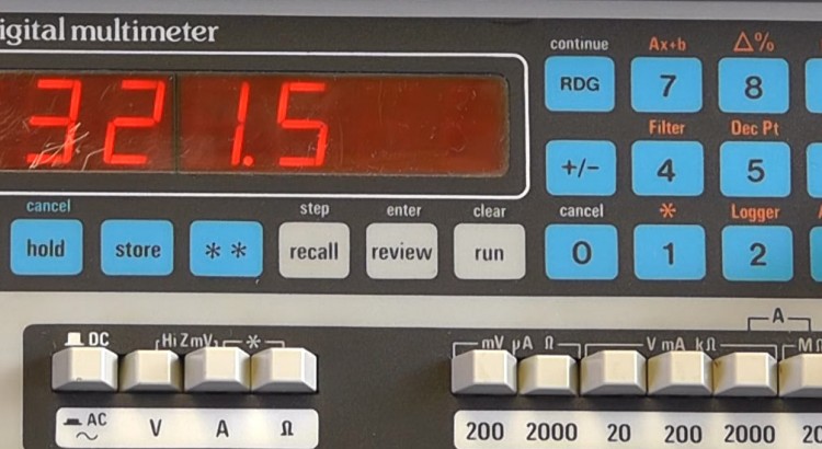
Review and teardown of the Thurlby 1905A Intelligent Digital Multimeter was designed and manufactured in the 1980’s by Thurlby Electronics Ltd. The meter is a 5½ digital manual ranging multimeter with keyboard programmable computing and data logging facilities. The basic accuracy is ±0.015% on the D.C. ranges.
Hi Louis,
I found a Thurlby 1905a multimeter in my late father’s craft room. It still works very well and is accurate enough for my hobby measurements.
Unfortunable the foil keybord didn’t work, but when I watched your video I got the necessary hints to do a “bypass” and now I can also use the log and computation functions.
Pretty cool if you remember the possibilities of 1983 …
With best regards
Franz
Hi Louis,
I have a 1905a which I recently acquired on eBay. It is a very sound meter despite its vintage and, although not calibrated for some years it does seem to be in spec and reliable. I am planning on bringing out the serial output header so I can log some data. The secret 6.5 digit mode is an extra bonus feature.
I also note that the there is an interesting feature on the panel – above the Ohms and A mode switches there is a bracket symbol and another *. Both Ohm and A keys can be latched down together. The manual makes brief notes about the ** keys as for ‘future development’ . I can’t determine if this key combination actually does anything – i wondered if it might have been for preliminary work on a 4 wire mode?
Hi Louis,
gladly I can call myself an owner of a 1905a. Unfortunately my unit is not equipped with neither the True-RMS module nor the RS232 module. Both of them appeared in your video and I would kindly ask you if you have some photos showing the copper side of both PCBs and if you have written down the PCB dimensions. I would really like to (re)build those two PCBs to fit in my 1905a. Besides not knowing where the tracks on the PCB are running, I couldn’t find any schematics of them in the www. Well, wouldn’t be a big deal if I had the above mentioned photos of the copper sides for ‘reverse engineering’ the schematics. Furthermore I tried to read the component values in your video that might be revealed – but I guess I’m not on the lucky side …
I excuse myself in advance in case you’re willing to disassemble your 1905a and make the photos I asked for and to read/measure the component values and the dimesions of the two PCBs missing in my 1905a.
Don’t get me wrong, I really appreciate and like your good work and hey, in exchange I can provide you with the complete schematics and PCB artwork when its done by me. May other profit from my work too. 😉
Currently I’m working on the LA160 which uses the same CPU PCB with some minor changes concerning component placements besides the firmware EEPROM. The main unit is already done, now I’m concentrating on all the available LC-pods and the LE32 thirty two channel extender module (where I’m also missing PCB photos and schematic by the way).