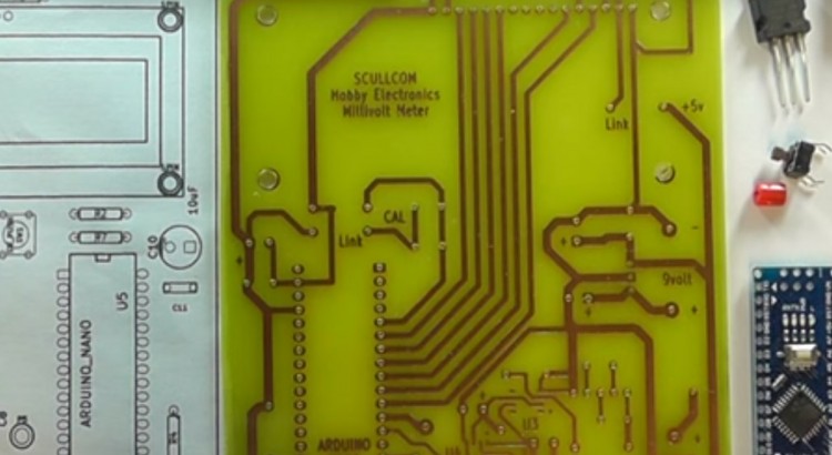
In this project we will design & build a 6½ Digit Millivolt Meter with calibration. In this first part of this project we design and build the circuit and do an initial test. In part 2 we will cover the software and final test and build.
Below are links to the full schematic and PCB artwork.
http://www.scullcom.com/Millivolt_Meter_Schematic.pdf
http://www.scullcom.com/Millivolt_Meter_PCB.pdf
Hi there,
Very interesting video. Im just wondering why you are using a 24 bit A/D when your reference is only accurate to about 12 bits.
Alan
Hi Alan,
Thanks for your comment. Sorry for the delay in answering as I missed your comment earlier.
A 24 bit ADC does not necessary assume an accuracy of that, but means it has a resolution of 24 bit and it was the resolution I was after, for comparing voltages. The accuracy of this project is dependent on the voltage reference source. The reference IC I used in this project was a ADR4540 (4.096v) which has an initial accuracy of ±0.02% and once the initial voltage is established it is very stable. Any error in initial voltage can be adjusted in calibration within software. The important thing here is the voltage drift from this initial stable voltage due to temperature and for this IC it is very low only 2ppm/°C which is equivalent to 0.0002%. Therefore the accuracy in this case would be ±0.0002%, which would mean the accuracy of this project would be virtually 5 decimal places, with a resolution of up to 6½ decimal places.
If you wanted to improve the accuracy of this you could use a temperature stabilised reference source such as the LTZ1000A which has a temperature drift of only 0.05ppm/°C which is equivalent to 0.000005%. Also the voltage reference is higher and would have to be adjusted. This type of reference source is used in 8½ Digit Multi-Meters and these reference IC’s are very expensive at around £45 plus and may also be difficult to source.
Regards,
Louis
Hi Louis!
I have found this project on youtube, it is great!
Why don’t complete this design like a complete DMM? i mean with ACV, resistor and current function?
Kind regards
mmmmmm I am sorry Louis to ask for a complete dmm….i realize that it could cost too much time and efforts…forget!
Kind regards!!!
thanks for a brilliant, amazing, engaging project