In this project we will design and build a Stair-Step Waveform Generator which gives a 5 volt peak-to-peak output with steps of 1 volt. Both a fixed oscillator and variable oscillator options will be included. A rotary switch will also give access to additional step waveforms.
A 74HC4017 Johnson Counter is used to drive a diode and resistor divider network to provide a stair-step waveform, giving an amplitude of 3 volt peak-to-peak. This signal is then coupled via a isolating capacitor to a buffer stage and amplifier which is set to give a final output waveform of 5 volt peak-to-peak. Each step is 1 volt.
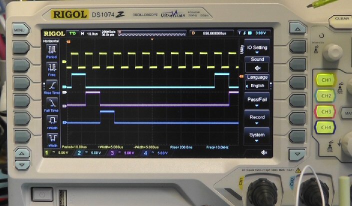
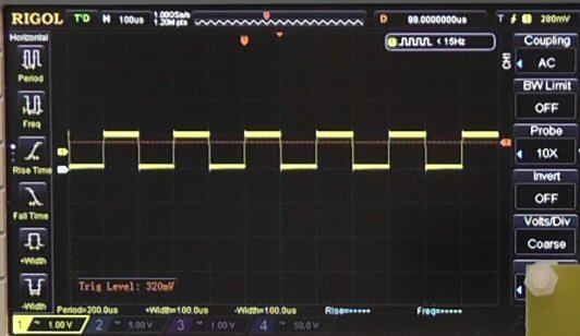
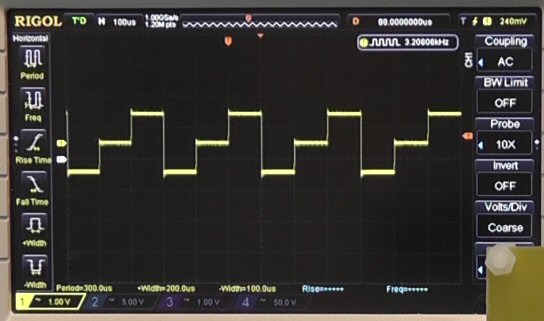
The image below shows the clock input to the 74HC4017 and the first three output signal Q0, Q1 and Q2. All pulses are 5 volt in amplitude.
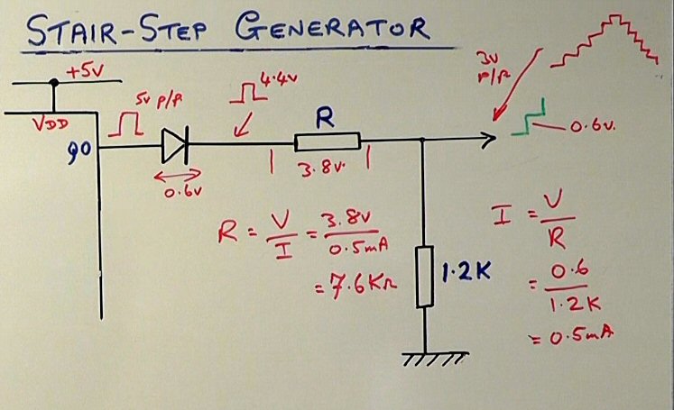
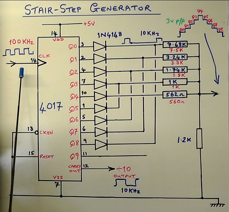
As the outputs from the 74HC4017 are feed via isolation diodes the amplitude of the pulses feed to the resistor divider network is about 4.4 volt (due to 0.6 volt diode voltage drop). The common earth return resistor in the divider network is fixed at 1.2K (in the final circuit this is replaced with a 1K in series with a 1K preset so as to provide some setup adjustment). Each of the other resistors in the network are calculated to provide a pulse output across the 1.2K which increment in steps of 0.6 volt to give a final stair-step waveform of 3 volt peak-to-peak.
The resistor values where calculated to be 7.6K, 3.2K, 1.73K, 1K and 560Ω and available resistor of 0.1% tolerance of 7.68K, 3.24K, 1.74K, 1K and 562Ω were used. If you do not have these values the I have found that standard values of 7.5K, 3.3K, 1.8K, 1K and 560Ω (all 1%) work well.
In the original circuit Q9 (pin11) was connected directly to ground. This was later changed (in Version 2) by adding a 10K resistor to ground.
Below are links to version 2 of the schematic and PCB artwork:
http://www.scullcom.com/Stair_Step_Gen_ver2_Schematic.pdf
http://www.scullcom.com/Stair_Step_Gen_ver2_PCB.pdf
The output stage buffer and amplifier uses a NE5532P Dual OP Amp which is powered from a +6 volt and -6 volt split supply which is generated using a TLE2426 “Rail Splitter” IC which produces a virtual earth splitting the 12 volt supply.
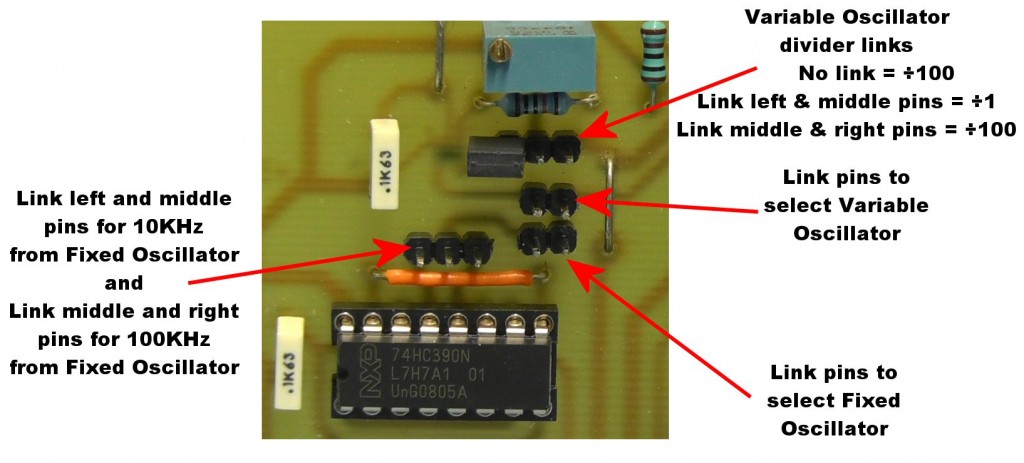
The Johnson Counter IC (74HC4017) can be supplied with a clock pulse from a fixed oscillator circuit using a 1MHz Crystal Oscillator module and a 74HC390 divider IC which gives either a 10KHz or 100KHz clock signal or a variable oscillator. The type of oscillator is selected by links of the PCB (which could be replaced with switches if required).
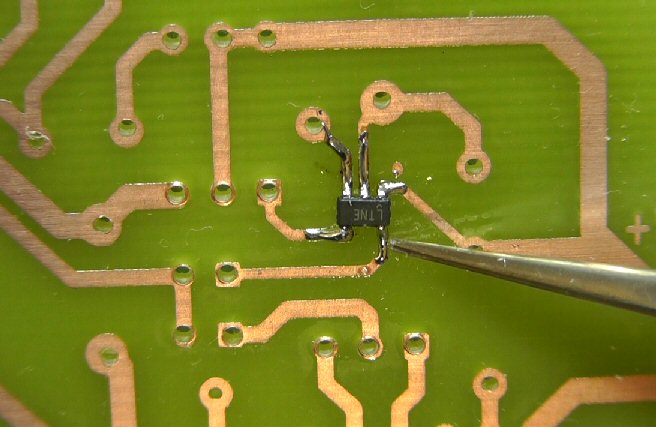
The variable oscillator uses a Linear Technology LTC1799 which is a precision oscillator in a small SOT-23 (5 pin) package. The frequency of the oscillator is simply set by an external resistor which in this project uses a variable preset (1MΩ preset in series with a 100KΩ resistor). The output of this oscillator can also be divided by 1, 10 and 100 by use of pin 4 of the IC; no connection results in ÷10, pin 4 to ground results in ÷1 and pin 4 to V+ (5v) results in ÷100.
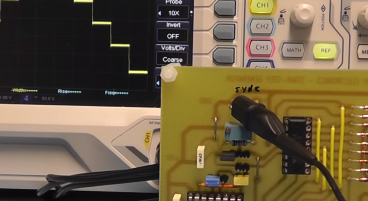
Below you see the LTC1799 soldered on to the PCB print side.
Below you see details of the links on the PCB to set both the type of oscillator to use and the frequency:
Parts List
C1, C3, C4, C6, C7, C10, C11 – 100nF
C2 – 2200uF
C5 – 470uF
C8, C9 – 10uF
D1, D2, D3, D4, D5, D6, D7, D8, D9 – 1N4148 (small switching diode)
JP1, JP2 – 2 pin SIL option link with link plug
JP3, JP4, JP5, JP6, JP7, JP8, JP9, JP11 – Wire Links
JP10 – 3 pin SIL option link with link plug
P1 to P6 – PCB terminal pins
R1 – 10K
R2, R10 – 100K
R3, R9, R11, R12 – 1K
R4 – 7.68K (± 0.1%) (RS stock No. 701-7673) or 7.5K (±1%)
R5 – 3.24K (± 0.1%) (RS stock No. 701-7550) or 3.3K (±1%)
R6 – 1.74K (± 0.1%) (RS stock No. 754-8758) or 1.8K (±1%)
R7 – 1K (± 0.1%) (RS stock No. 701-7383) or 1K 1K (±1%)
R8 – 562Ω (± 0.1%) (RS stock No. 701-7305) or 560Ω (±1%)
RV2 – 1M Potentiometer or Preset
RV3 – 1K Preset
RV4 – 10K Preset
S1 – Rotary Switch, 6 Way, Through Hole (RS Components Ltd stock No. 665-196)
SW2 – Single Pole ON-OFF-ON switch or 3 pin SIL option link with link plug
U1 – LTC1799 Linear Technology precision oscillator in SOT-23 (5 pin) package
U2 – LM7812 12 volt regulator
U3 – LM7805 5 volt regulator
U4 – 74HC4017 Johnson decade counter with 10 decoded outputs
U5 – TLE2426 Texas Instruments, Supply Rail Splitter, “virtual ground” in TO-92 package
U6 – NE5532P Texas Instruments, Dual Op Amp
U7 – 74LS390 Texas Instruments 4-stage, Decade, Decade Counter/Divider
XTL1 – 5V 1MHz Crystal Oscillator Modules Through Hole (DIL-14 format) available on eBay from seller ha5ia for £2.98. Link below:
http://www.ebay.co.uk/itm/181176576561?_trksid=p2057872.m2749.l2649&ssPageName=STRK%3AMEBIDX%3AIT
1 x 8 pin DIL socket
2 x 16 pin DIL socket
1 x 15v or 18v DC power adapter
Additional Features
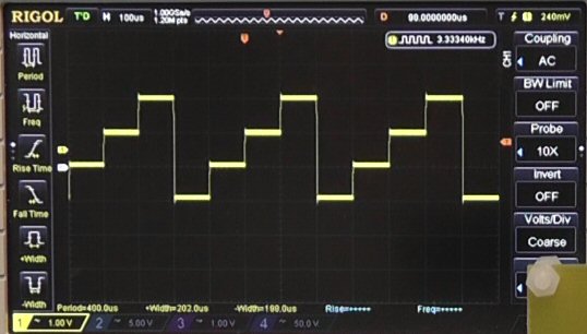
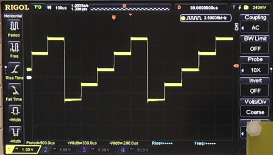
This project also provide step waveforms of 1, 2, 3 or 4 steps (as shown below) by use of a rotary switch to connect the master reset on the Johnson Counter IC with different outputs.
Nice project, well explained but one thing I am missing -what is the usual implementation for a staircase generator? what can it be used for?
Can be used in curve tracer to plot diodes, bjt, fet, mosfet curve on scopes.
Well, I can tell you one use for it. Vintage TV enthusiasts (videokarma.org) can use it as a test signal generator.
Its cheap and easy to build. There’s another circuit out there that uses a 4060 chip, which has an oscillator built in. But it only does the stairstep in one direction only. Of course, you would need a 15750 Hz. clock to make it work that you can get from a 555.
It doesn’t need vertical since you won’t be locking it to another source. Its useful in checking B&W balance, smear (video response) and as a general signal source.
Love your projects and your YouTube Videos!!! I’m a big fan, keep up the great work.
I wish you would design a Mark2 version of the Stair-Step Generator which uses the
Arduino Nano and IC controls instead of the large selector switch. I want to mount
your project into a case that I can stack onto my workbench with your other
projects, one on top of each other.
Hi Michael,
Thanks for your comments.
At the moment I am busy on some other projects when I have some spare time.
I take note of your request for a Mark2 version of the Stair-Step Generator and may have a look at that when I have more time.
Regards,
Louis
This is a great circuit – many thanks.
A quick question about the Electrolytic Cap – 10uF C9. As I understand it, it’s used to remove DC offset before passing on to the buffer NE5532P? I am puzzled about the orientation/polarity of the component – would you be able to shed some light on this? That would be very helpful. Many thanks
Do you sell a PC board? Or a working unit?
Hi..I am subscribed to your YouTube channel. I built the Johnson counter to diode and resistor array as per your design (fed this from a regulated 5V dc supply and used a 100KHz clock crystal module to give the clocking pulse on pin 14 of a 74HCT4017 Johnson counter). When I tested the output at the common point (after the resistors), I got no waveform at all. I rechecked everything. Everything looked fine. I then just tried reversing the diode corresponding to Q0 ( in desperation really just to see with no logical reason why it might work) and blow me if I did not get quite a good staircase output waveform ! This was a breadboard build. The only thing wrong with the staircase was waveform that the highest voltage output (top of the staircase) was two pulses width. Any ideas what is happening here? I am perplexed by it.