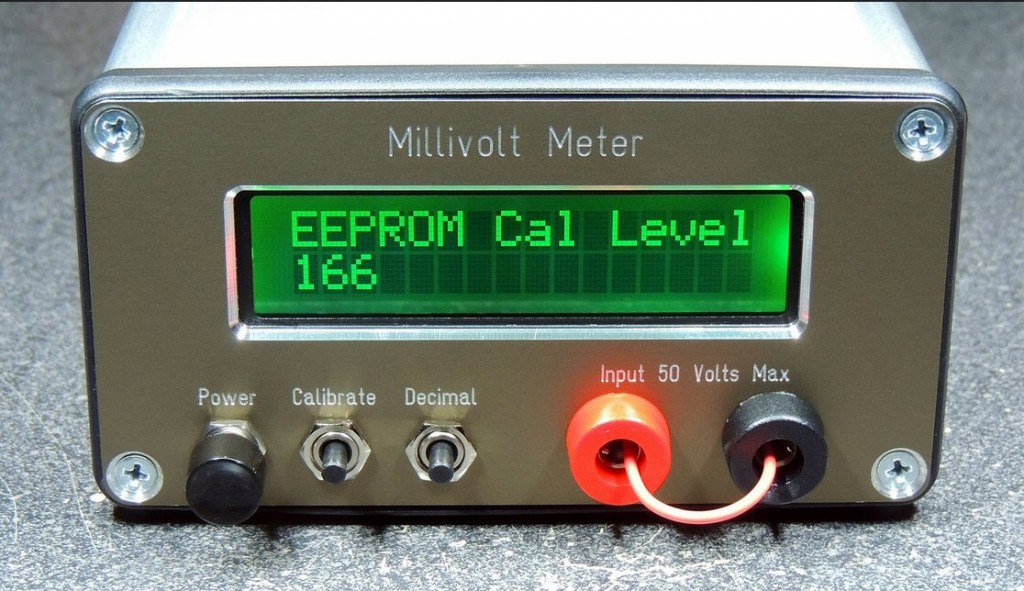
This is a quick update on the Millivolt Meter Project. Changes to the input circuitry and a new software version.
Latest schematic and PCB can be downloaded from link below:
http://www.scullcom.com/Millivolt_Meter_Ver4.pdf
http://www.scullcom.com/Millivolt_Meter_PCB_Ver4.pdf
Below are links to the new software (version 7.0):
http://www.scullcom.com/SHMMSimple.ino
Also the GitHub link below:
https://github.com/int2str/SHMMSimple
PCB available from OSH Park
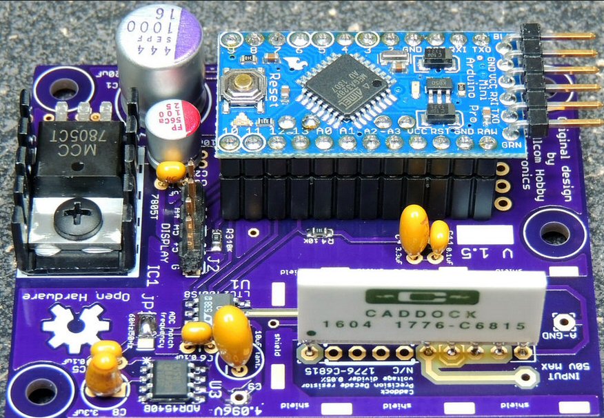
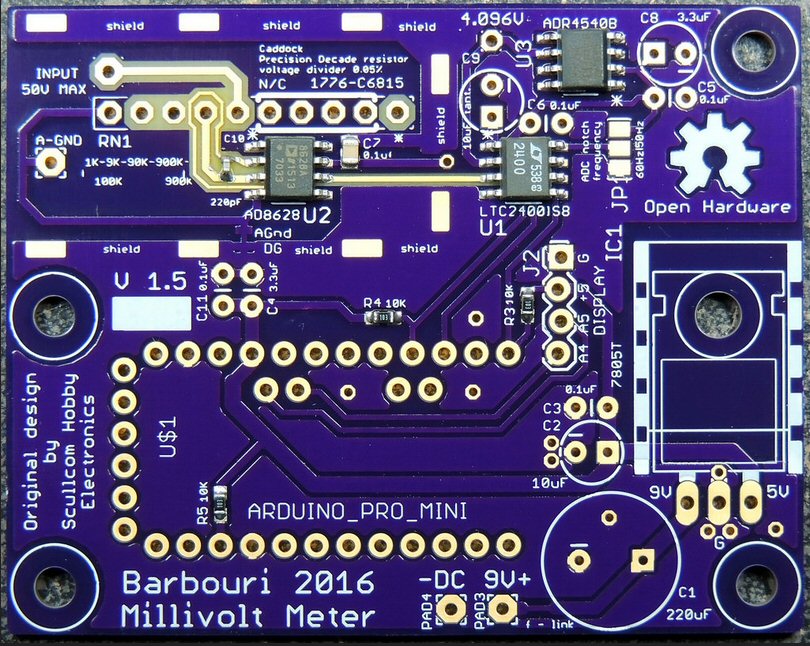
A PCB (using surface mount components) designed by one of my subscribers “pbreviceps” (Greg). Who left a comment in Part 4 of this project. Greg has taken my design and software and produced a very high quality PCB (double sided). Check out this PCB at the following link:
https://www.flickr.com/photos/barbouri/26392316563/
This PCB is available worldwide (free shipping) from OSH Park for just a few dollars. Check their link below for this project:
https://oshpark.com/shared_projects/qgv0fpKN
The PCB design file is also available on this webpage to download.
https://644db4de3505c40a0444-327723bce298e3ff5813fb42baeefbaa.ssl.cf1.rackcdn.com/0fa8729a07e906a84e6cf5762d45a390.brd
Greg used Arduino Pro Mini on the board, and a Caddock voltage divider resistor as I showed in my Part 1 of this project. The display was changed to a I2C LCD (driven by A4 and A5 from the Arduino) this needs slight change to the software code.
As you will see on the PCB and input “guard ring” is used at the input of the OP Amp from the input resistor divider.
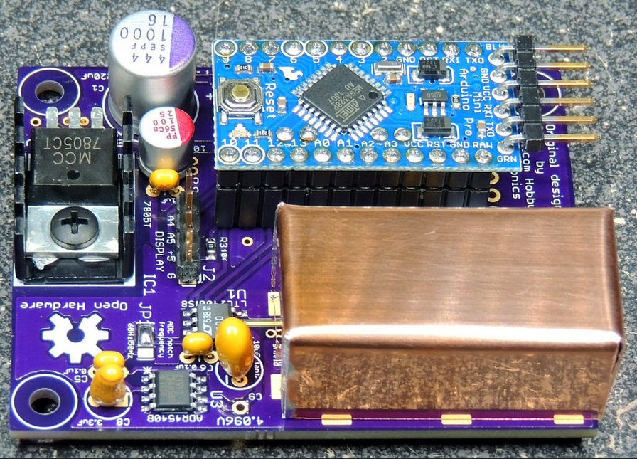
Copper shielding was added to the input circuitry.

Great design, and after the milli-ohm meter will be my next tool to build.
One comment though. You are using the typical way of trying to debounce a switch. If you think about it, only one edge will be effected by the R/C (when the C charges) but the other one will “spark” because the switch will short-circuit the charged capacitor, making the problem worse. If you add a series resistor between the switch and the capacitor, you will have created an R/C for both edges. All you need to do then is to add a little software delay to get “past” any remaining bounce, depending on the speed of the processor.
Thanks for sharing your ideas in such a professional way!
Paul
Hello,
I’m going to build the Millivolt meter, but I have a few questions. I don’t see the 4.096V trim pot on
your schematic, that I down-loaded. The PCB schematic #4 has a 1uf cap on the output of the AD8628, not
the 10uf cap you mentioned in the Youtube video, and no series resistor which is discussed in the comment
section. Do you upgrade your PCB schematic, and can I get an upgraded schematic. For my use I don’t care
about going to the version 5 PCB. I prefer the simpler Nano design.
I need to go to 100V, so I’m going to add a 10Mohm to the Caddock input and use a switch to change ranges.