In this project we will design and build a pulse generator using a LTC6992 from Linear Technology. In this first part we will test the functions of this IC to change both frequency and duty cycle (pulse width). Other parts to this project will build on this basic design with additional features and modifications/improvements.
The LTC6992 is a Voltage-Controlled Pulse Width Modulator with selectable frequency ranges. There are 4 variants of this IC which differ in their minimum/maximum duty cycle control. The version we will be using is the LTC6992-2 (duty cycle range from 5% to 95%).
The voltage on pin 3 is held constant at 1 volt by the internal voltage reference. The amount of current from the SET pin (pin 3) determines the frequency of the master oscillator by varying the resistor at pin 3. The current swing should be between the ranges of 1.25μA and 20μA, this means that the Rset resistor value at pin 3 can range from 800KΩ maximum to 50KΩ minimum.
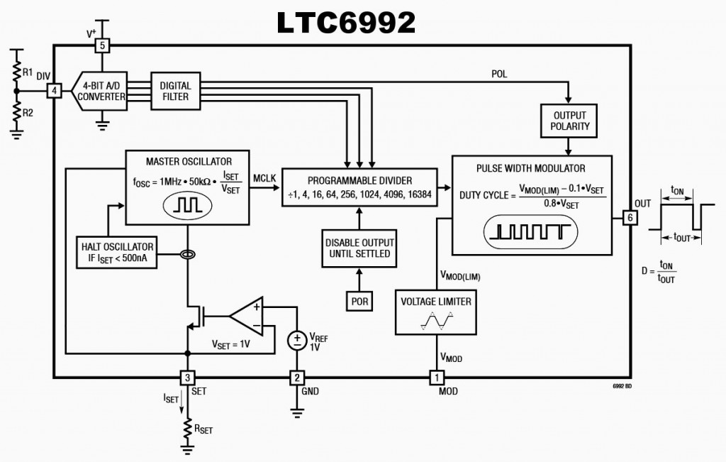
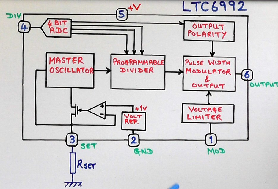
Above is a more detailed view of the LTC6992. The programmable divider is control by the first 3 bits from the internal 4 Bit ADC, with the most significant bit controlling the output pulse polarity.
The frequency of the oscillator is set by a variable resistor from pin 3 of LTC6992 to ground. It is important that the connecting leads are a short as possible otherwise you will get jitter and instability at the higher frequency ranges.
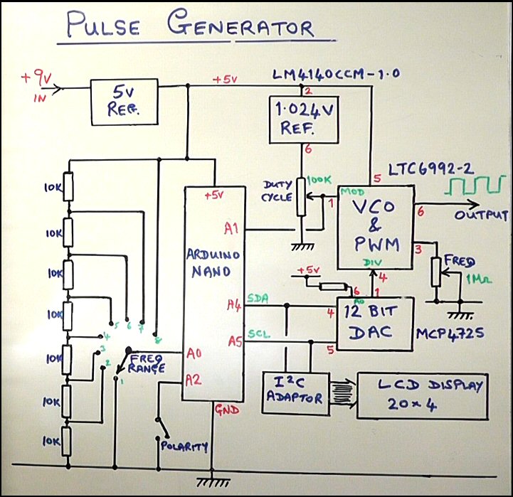
The pulse width (duty cycle) is set by applying a voltage to pin 1 of the LTC6992. The voltage range should be from 0 to 1 volt so we use a LM4140CCM-1.0 to provide a precision 1.024V which is then fed to a 100K pot, the centre of which then feeds pin 1 of the IC.
The voltage to control the frequency ranges and output pulse polarity is provided by a MCP4725 (12 Bit DAC).
The I2C bus of the Arduino Nano (A4, A5) are used to control both the MCP4725 (12 Bit DAC) and the 20×4 LCD (via a I2C Adapter).
The frequency range selector switch provides a voltage to A0 of the Arduino which is then used in software to select the required data for the MCP4725.
A simple switch from A2 of the Arduino to ground controls the output polarity of the signal. A2 in this case is used a simple digital input and its internal pull-up resistor is selected in software.
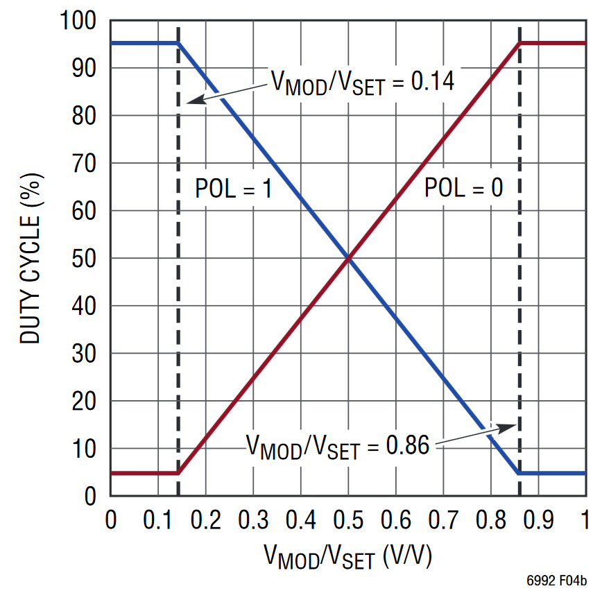
The above graph shows the relationship between voltage on pin 1 of the LTC6992 and output pulse duty cycle. It shows the swing for the LTC6992-2 (5% to 95%).
Below are links to the Schematic, PCB, PCB layout and Arduino software.
http://www.scullcom.com/Pulse_Gen_Schematic_Part1.pdf
http://www.scullcom.com/Pulse_Generator_PCB.pdf
http://www.scullcom.com/Pulse_Gen_Layout.pdf
http://www.scullcom.com/Pulse_Generator_ver1.ino
Note the Arduino software uses LiquidCrystal_I2C.h and Adafruit_MCP4725.h libraries which you need to be installed. Links to library downloads below:
https://bitbucket.org/fmalpartida/new-liquidcrystal/downloads/LiquidCrystal_V1.2.1.zip
https://github.com/adafruit/Adafruit_MCP4725/archive/master.zip
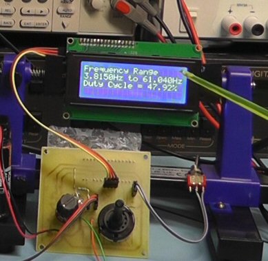
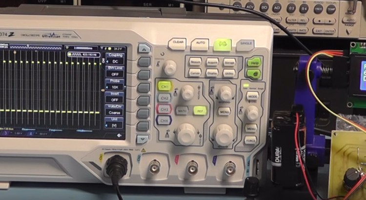
Display shows frequency range and duty cycle level
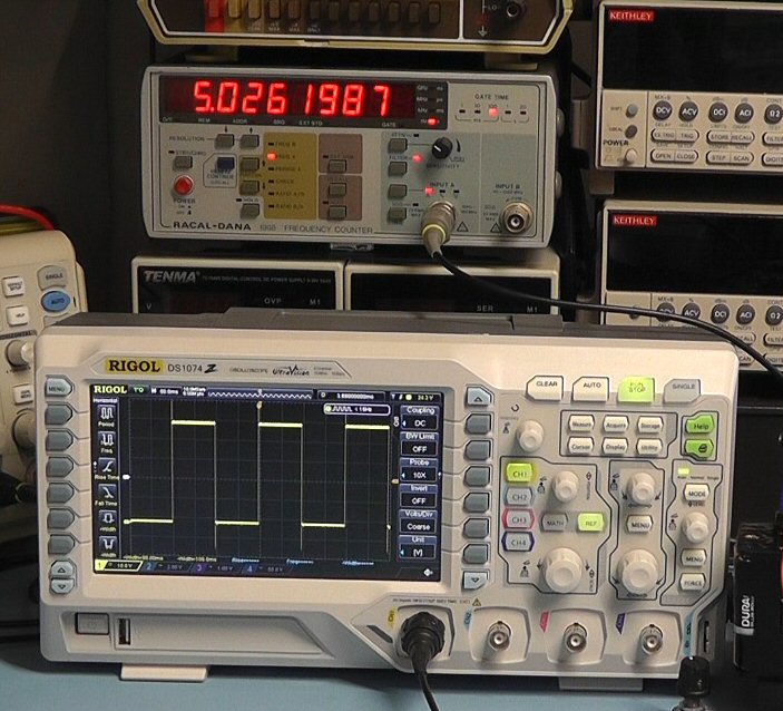
Sample of waveform output
are you going to be designing projects that we can utilize this equipment in so that we can learn when to use it?
Hi Louis, I’m wondering why there does not seem to be a Part 2 to this very interesting and useful ?
Hi Erik,
Sorry I got side tracked I will try and get back to it later. Although I am considering an alternative Pulse Generator project. Its just finding time to do everything I want to 😉
Regards,
Louis
A second part would be great! I have watched the first part more than once since least year. Really nice and useful content. Thank you, Louis.
Thanks Roberto,
For your comment. I am busy with other work at the moment but it on my things to do list.
Best regards,
Louis
I intend using this ic for controlling the output of a boost or buck converter, and also to use the ic to control the output voltage of SMPs, but still don’t understand how it works well enough.